GC Technical Tip
Level: Advanced
GC Backflushing: “Wait, That’s a Legit Technique?"
You may have heard of flushing or “flushing out” a GC column. This can mean a variety of approaches to either cleaning or destroying a GC column. Some GC systems offer built-in backflush functionality, while others implement backflush using dedicated flow devices and a second pressure source/pneumatic channel.
Solvent flushing involves forcing liquid solvent through a GC column as a general ‘cleaning’ strategy. This is usually not recommended, as it can redistribute non-volatiles and leave residues upon drying. Any solvent rinsing should be evaluated case-by-case, based on column chemistry and contaminant type.
"Backflushing" in the traditional sense involves carrier gas, and requires an instrument that can host two GC columns that feed into a “T-junction.” One column leads from the injection port to a T-junction (guard column, left in Fig. 1), and a second column leads from the T-junction to the detector (analytical column, right in Fig. 1). This is one common backflush configuration; other instruments might implement backflush using dedicated flow devices and a second pressure source to reverse flow in a selected section of the column. Depending on the GC hardware, backflush can be implemented as pre‑, mid-, or post‑column backflush using dedicated flow devices and a second pneumatic channel.
In the setting we are considering here, when a sample is first injected, it enters the guard column, which flows through the T-junction and into the analytical column on the right. During this process, the T-junction has a very gentle flow of gas (B mL/min), whereas the guard column has a faster flow of gas (A mL/min). This ensures the net flow is directed through the analytical column on the right with a flow of (A + B) mL/min. (Fig. 1).
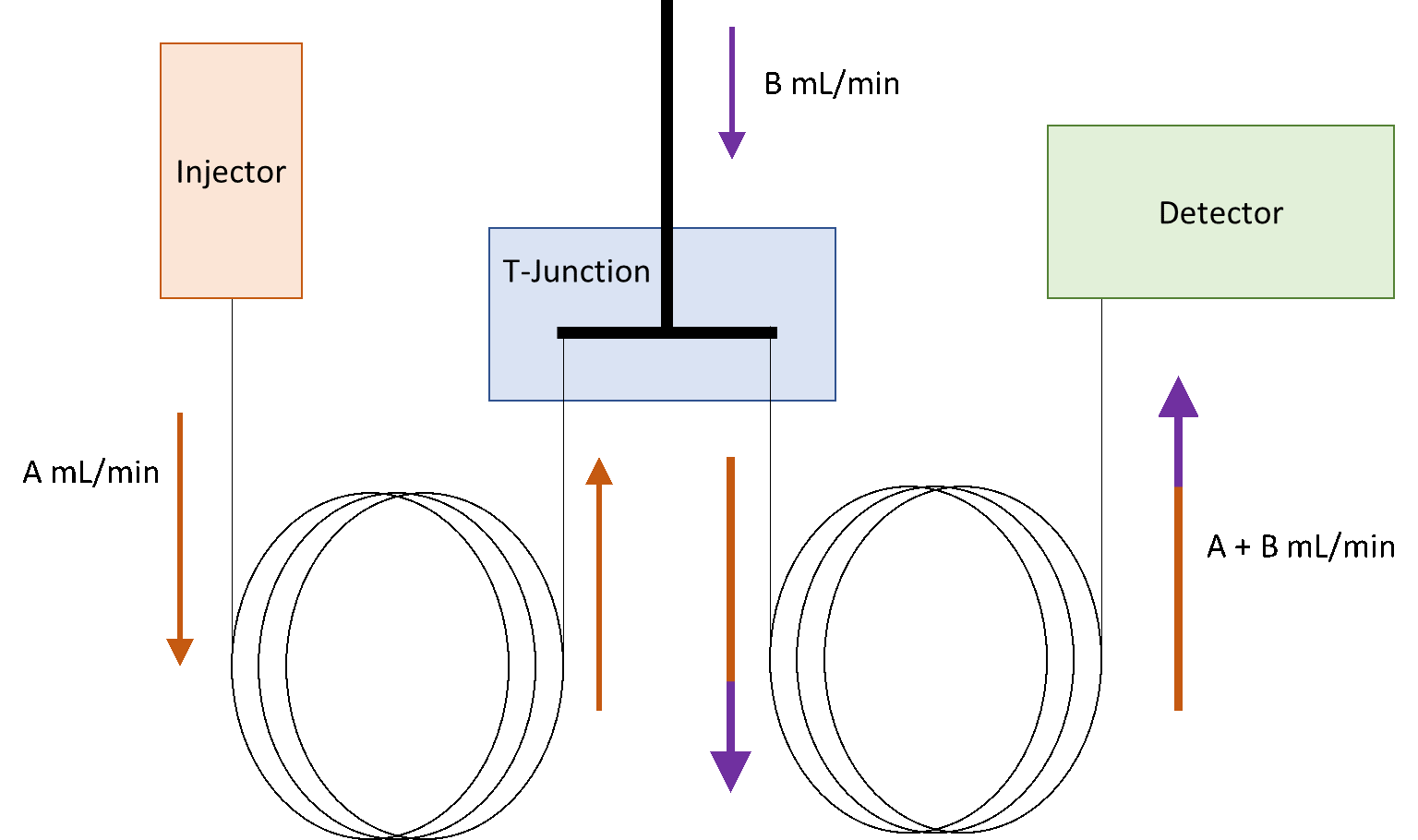
Fig 1: Traditional GC backflush setup (forward-analysis mode).
Backflush is typically initiated after the last analyte of interest has eluted, with a small safety margin to avoid cutting late-eluting targets. Once the analytes have all transferred into the column on the right, the inlet pressure/flow is reduced relative to the auxiliary pressure so that the flow at the T-junction becomes dominant, reversing flow in the guard column while maintaining forward flow to the detector. At this point the flow from the top of the T-junction has a much higher flow-rate. (Fig. 2).
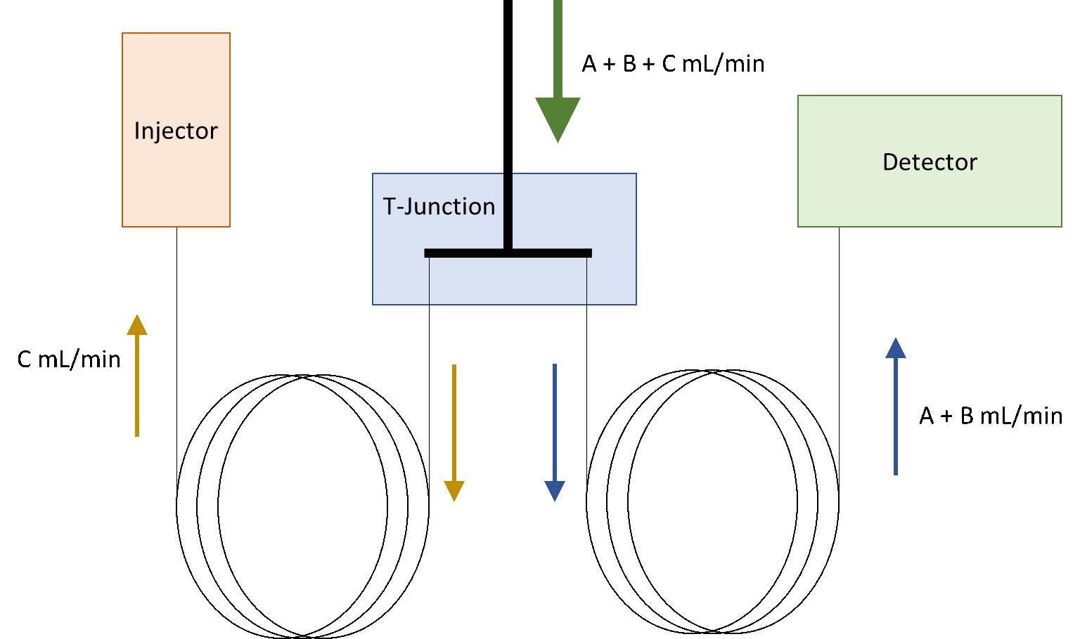
Fig 2: Traditional GC backflush setup (backflush mode).
The flow (A + B + C mL/min) into the T-junction is strong enough to keep the (A + B ) mL/min flow through the column on the right, while forcing gas through the guard column on the left and back into the injector (C mL/min). The column temperature rises to reach a point at which the semi-volatiles and non-volatiles from the injection get baked out without having to travel through the entire length of the column. In other words, the semi-volatiles and non-volatiles are forced back out into the injection port and then vented through either the split vent or septa purge. A "backflush cycle" will run through 2 - 10 column volumes of carrier gas flow for the guard column on the left while the oven remains at high temperature. Note: Because backflush sends high boilers back to the inlet, liner and split vent components may require more frequent maintenance, depending on matrix load.
This technique is particularly valuable for on‑column injections (where essentially all injected material reaches the column), but it is also widely used with PTV/MMI and split/splitless inlets to improve robustness for dirty matrices and to reduce cycle time and maintenance.
An example would be an oil sample. Why use a backflushing instrument instead of simply trimming the beginning of the column? The advantage of the backflush is to avoid having to detach a column for a snip, only to then re-attach the same column. A column cannot experience many on-column injections before a trim would normally be needed, whereas the process of trimming is obviated altogether with formal backflushing.
Generally, it is recommended that the guard column is either a fused silica tubing (uncoated) or a column whose stationary-phase matches the analytical column on the right side. The lengths and IDs of the two columns can be different, however, try to match the ID of the two columns as matching ID values will help to evenly and consistently split the flow of entering the T-junction (A + B + C mL/min) during the backflushing segment of the method. We advise against solvent flushing and suggest using Z-guards and phases that would be applicable to a proper backflushing system.
We hope you found this tip useful. Stay tuned for next month's tech tips!
Zebron Z-Guard GC Columns
Protect and extend column lifetime
• Individually QC tested to ensure the highest level of quality
• Extend column lifetime by preventing stationary phase damage
• Improve separation and peak shapes (especially early elutors)
• Improve sensitivity and accuracy of quantitative results
• Available as individual guard columns or as complete kits with connectors

GC Column Care and Installation Guide
Ensure your Zebron GC column is properly installed and maintained with this handy guide to GC column care.
Phenomenex, the P icon, and the Phenomenex product and service marks mentioned herein are trademarks or registered trademarks of Phenomenex, Inc. in the United States and/or other countries. All other trademarks are the property of their respective owners. One or more authors are affiliated with Phenomenex, Inc. FOR RESEARCH USE ONLY. Not for use in clinical diagnostic procedures. © 2026 Phenomenex, Inc. All rights reserved.

Phenomenex is a technology leader committed to developing novel analytical chemistry solutions that solve the separation and purification challenges of researchers worldwide.
CONNECT WITH US